
ProQual Level 5 – Master Photo and Diagram Interpretation Tasks
Level 5 Passive Fire – Diagram Guide Interpretation Tasks
Table of Contents
Knowledge Guide: Visual Inspection, Diagram Interpretation, and Photographic Evidence
1. The Power of Visual Evidence in PFP Inspection
In the vocational realm of Passive Fire Protection (PFP), your eyes are your primary diagnostic tool. The ability to look at a physical installation—or a photograph of one—and instantly cross-reference it with a complex 2D technical diagram is the hallmark of a competent Level 5 Inspector. In many ways, passive fire protection is the ultimate defense strategy for a building. Think of fire compartmentation like a fortified zone; if a hazard, defect, or non-compliance lands in your territory, your objective as an inspector is to completely zero it out before it compromises the entire structural integrity.
A photograph is no longer just a memory aid; it is a legally binding snapshot of compliance or failure. Your competency relies heavily on observation, interpretation, and formulating immediate corrective actions based on what you see. Capturing and interpreting Photographic Evidence—images showing proper installation, non-compliance issues, and corrective actions —is how you prove the reality of the site condition at a specific moment in time.
2. The UK Statutory Landscape for Visual Records
When you monitor project compliance with legal and statutory requirements in relation to passive fire protection, you are operating strictly within UK law.
- The Building Safety Act 2022 (BSA): The BSA requires the creation of the “Golden Thread” of building information. Photographs are the most irrefutable components of this thread. During the Gateway 2 (construction) and Gateway 3 (completion) phases overseen by the Building Safety Regulator (BSR), photographic evidence is routinely demanded to prove that the “as-built” condition matches the “as-designed” specification.
- Regulatory Reform (Fire Safety) Order 2005 (FSO): The Responsible Person must maintain the building’s fire safety. Without high-quality, date-stamped photographic evidence from the construction phase, future fire risk assessors cannot verify hidden elements (like fire stopping above a suspended ceiling), leading to intrusive, destructive surveys later on.
- Regulation 38 of the Building Regulations (England and Wales): This regulation dictates that fire safety information must be handed over to the ‘Responsible Person’ at the completion of a project or when the building or extension is first occupied. High-resolution photographic records of PFP installations directly satisfy this legal handover requirement.
3. The Science of Photographic Observation and Interpretation
Taking a photo is easy; capturing evidence requires vocational skill. When interpreting site images or taking your own, you must evaluate them against several strict criteria:
- Context and Location: A close-up image of a perfectly sealed pipe is useless if you cannot prove where it is. A competent inspector always takes a “macro” shot showing the broader wall, gridlines, or doorways, followed by a “micro” shot detailing the seal.
- Scale and Measurement: Visual distortion can make a 50mm gap look like a 10mm gap. Photographic evidence should ideally include a physical reference, such as an inspector’s tape measure or depth gauge placed within the frame, proving the annular space or sealant depth.
- Clarity and Lighting: PFP installations are often in dark risers, ceiling voids, or basements. Poor lighting hides defects. Interpretation requires clear illumination to spot hairline cracks in ablative coatings or gaps in mineral wool friction fits.
4. Translating the Manufacturer’s Diagram to Site Reality
To spot a non-compliance, you must first understand what compliance looks like. Manufacturers provide tested detail diagrams. These are highly specific, annotated engineering drawings. Your task is to play “spot the difference” between the theoretical diagram and the practical site photo.
When reading a PFP technical diagram, you must systematically interpret the following elements and look for their physical counterparts in the installation photograph:
- The Substrate: Does the diagram specify 100mm rigid masonry, but the photo shows flexible plasterboard? This is an immediate, critical failure. The system will not perform as tested.
- The Service Type: Does the diagram show a copper pipe, but the photo shows a PVC pipe? Copper conducts heat; PVC melts. They require entirely different intumescent strategies.
- The Support Distances: This is a frequently missed defect. The diagram will state: “First service support to be located no further than 500mm from the face of the seal.” In a fire, if a heavy steel pipe is unsupported, it will sag, putting immense leverage on the fire seal and ripping it out of the wall. When interpreting a site photo, you must look at the wall seal, and then trace the pipe back to see where it is physically clamped to the ceiling or floor soffit.
- Fixing Specifications: A diagram for a fire collar might show four distinct anchor points. If the site photo shows only three screws, or worse, drywall screws instead of the specified steel masonry anchors, the collar will detach during a fire.
5. Common Visual Defects in PFP Installations
When reviewing site photos, a Level 5 Inspector is trained to recognize specific visual triggers that indicate non-compliance:
- The “Pink Foam” Violation: Seeing standard pink or yellow expanding polyurethane foam used as a primary fire stopping material around service penetrations. Unless specifically tested as part of a highly restricted system, this is almost always a non-conformance. It provides no insulation (I) value and melts rapidly.
- Unpasted Batt Edges: Mineral wool fire boards (batts) must have an ablative coating applied to all cut edges before being friction-fitted into an opening. If a photo shows raw, yellow mineral wool abutting the concrete slab or the penetrating service, smoke and toxic gases will bypass the seal at those microscopic junctions.
- Incorrect Orientation of Pattress Fits: Sometimes, fire batts are face-fixed (pattress fitted) over an opening rather than friction-fitted inside it. The diagram will specify a minimum overlap (e.g., 100mm onto the surrounding substrate). A photo showing a batt barely covering the hole with a 20mm overlap is a severe defect.
- Sealant Slump: If a photo shows the intumescent mastic sagging or drooping out of the annular space, it indicates the gap was too large for a pure mastic seal, or the mastic was applied without the required mineral wool backing material.
6. Formulating Corrective Actions
Observation and interpretation are only the first two steps. The final, critical step in your professional judgment is determining the corrective action. If an image reveals a defect, how do you fix it?
- Can the defect be remediated (e.g., adding missing ablative mastic to an edge)?
- Does the installation need to be completely stripped out and redone (e.g., if standard silicone was used instead of intumescent acrylic deep inside the annular space)?
- Does the contractor need to provide an entirely different tested detail because the as-built opening size exceeds the maximum parameters of the current diagram?
By mastering this visual interpretation cycle—observe the reality, compare to the diagram, identify the gap, and prescribe the fix—you ensure that the passive fire protection will perform exactly as designed when lives depend on it.
Assessor-Prepared Scenario: Photo & Diagram Interpretation
Context:
You are reviewing documentation for a newly constructed hospital wing in Birmingham.
The System Required:
A fire-stopping seal for a 300mm wide steel cable tray penetrating a 120-minute (EI120) fire-rated rigid blockwork wall.
Provided Assessor Materials (Simulated Visuals):
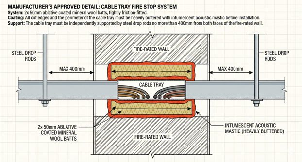
- Document A (The Diagram): The manufacturer’s approved detail states:
- System: 2x 50mm ablative coated mineral wool batts, tightly friction-fitted.
- Coating: All cut edges and the perimeter of the cable tray must be heavily buttered with intumescent acoustic mastic before installation.
- Support: The cable tray must be independently supported by steel drop rods no more than 400mm from both faces of the fire-rated wall.
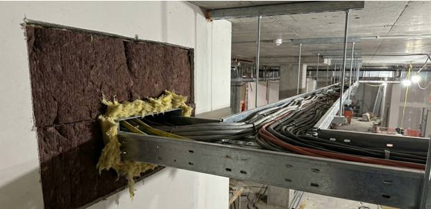
- Document B (The Site Photograph): You examine a photograph submitted by the contractor claiming the work is complete. You observe the following in the image:
- The 50mm ablative batts are installed.
- Around the perimeter of the steel cable tray, where it passes through the batt, you can see jagged, raw yellow mineral wool. There is no white intumescent mastic sealing the junction between the metal tray and the batt.
- You look down the length of the cable tray in the photo. The first visible steel support bracket holding the tray to the ceiling is located approximately 1.5 meters away from the fire wall.
Learner Task: Photographic Evidence Log Generation
To meet the assessment requirements for Unit 2, you must compile documents as evidence to demonstrate your competency. For this task, you will generate evidence strictly falling under category 2. Site Inspections and Monitoring Records—specifically, creating a formal record for Photographic Evidence.
Your Task:
Create a formal “Photographic Evidence Interpretation Log” based only on the simulated Document A (Diagram) and Document B (Photograph) described above.
Your Log must include:
- Image Metadata: Fictionalize the project details, date, time, and specific location of the photograph.
- Observation: A precise description of what you “see” in the photograph regarding the installation.
- Interpretation against the Diagram: Clearly state the discrepancies between the manufacturer’s specified diagram (Document A) and the observed site reality (Document B). Highlight the specific hazards these defects pose in the event of a fire (think about smoke passage and structural leverage).
- Recommended Corrective Actions: Detail the exact step-by-step instructions the contractor must follow to “zero out” these non-compliances and bring the installation up to the agreed quality standards.
Submission Guidelines
Ensure your submitted documentation adheres to the final notes from your Assessment Plan:
- Authentication: Ensure that all documents are authentic, relevant, and properly organized for easy reference by inserting your name and signature after writing PROVIDED BY/ PREPARED BY either at the start or end of EACH document.
- Data Protection: Confidentiality is crucial – anonymize sensitive information before submission.
- Presentation: Use clear indexing and labeling for smooth assessment review. Title your document clearly (e.g., Evidence 2.3: Photographic Evidence Interpretation – Cable Tray Penetration).