Testing & Inspecting NVQ Level 3: Process Flow Task
Table of Contents
Introduction and Purpose
In construction projects, many activities involve complex sequences of tasks and procedures. Mismanagement, skipped steps, or poor communication can lead to safety incidents, delays, and non-compliance with UK regulations. A process flow diagram helps structure complex procedures into a clear visual sequence, making it easier to understand, communicate, and execute tasks accurately.
This Knowledge Providing Task focuses on teaching learners how to:
- Break down work activities into sequential steps.
- Identify the required resources and dependencies at each stage.
- Visualize processes to improve clarity and procedural compliance.
- Ensure processes align with UK Health & Safety legislation, CDM Regulations 2015, and industry best practice.
By completing this task, learners will be able to convert written procedures into clear, visual flow diagrams, supporting better planning, resource management, and communication in a construction environment.
Understanding Work Activities and Resource Sequencing
Before creating a process flow diagram, learners must identify:
- The key activities involved in the procedure.
- Resources required for each activity (personnel, tools, equipment, materials).
- Dependencies between activities.
- Potential risks and control measures.
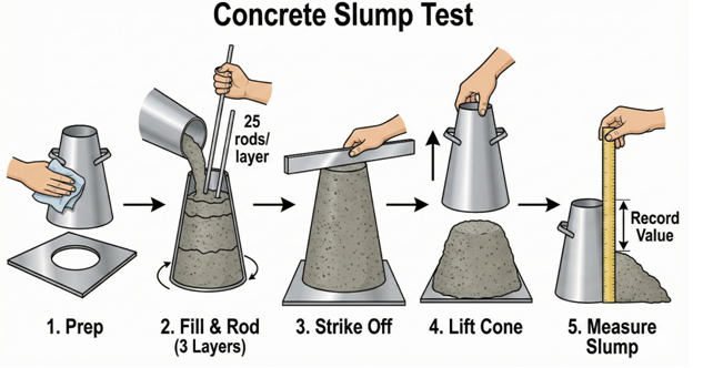
Example: Concrete Testing Process
| Step | Work Activity | Resources Required | Dependencies | Notes |
| 1 | Collect concrete sample | Sampling equipment, safety gloves, goggles | Concrete poured | Comply with BS EN 12350 |
| 2 | Transport sample to lab | Sample container, trolley | Step 1 completed | Avoid contamination or temperature changes |
| 3 | Slump test | Slump cone, base plate, tamping rod | Step 2 | Follow BS EN 12350-2 |
| 4 | Compression test | Cubes, curing tank, compression testing machine | Slump test completed | Record results accurately |
| 5 | Record and report results | Lab forms, computer | Step 4 | Ensure compliance with project specification |
Small Visual Representation (Flow Diagram Example):
[Collect Sample] -->[Transport to Lab] -->[Slump Test] -->[Compression Test] -->[Record Results]
Learners will later draw this in a proper flowchart format.
Identifying Dependencies and Influences
Some activities are interdependent. Learners must understand:
- Which tasks must occur sequentially.
- Which tasks can run in parallel.
- How resource availability may affect scheduling.
Example:
- Slump testing cannot occur until the sample is collected.
- Resource bottlenecks (e.g., one compression testing machine) may delay subsequent steps.
Illustration:
Step1 -->Step
\
\-->Step3a (parallel optional task)
This visual mapping highlights where planning adjustments are needed if resources are unavailable or delays occur.
Process Flow Construction Principles
When creating a process flow diagram, learners should:
- Start with a clear objective: Define the purpose of the process (e.g., “Ensure concrete meets strength requirements”).
- List all steps: Write down all activities in the correct sequence.
- Identify decision points: Include Yes/No or approval stages (e.g., “Does sample meet specification?”).
- Assign resources: Note personnel, tools, or materials required for each step.
- Highlight compliance requirements: Include UK legislation references where applicable.
- Use standard flowchart symbols:
- Ovals: Start/End
- Rectangles: Process step
- Diamonds: Decision point
- Arrows: Sequence flow
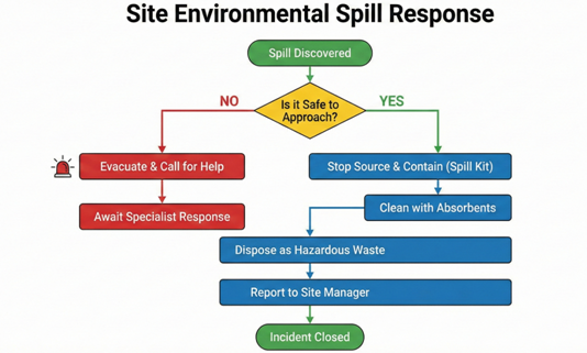
Example: Simple Spill Response Process Flow
[Spill Detected] -->[Alert Team] -->[Is PPE Available?] --> Yes -->[Contain Spill] -->[Clean Up] -->[Dispose Waste]
\
No -->[Obtain PPE] -->[Contain Spill]
This small diagram helps learners visualize the correct sequence, including conditional steps.
Scenario-Based Process Flow Construction
Learners will practice creating process flows for the following scenarios:
Scenario 1: Concrete Testing Process
- Break down the testing process from sampling to reporting results.
- Identify all tools and personnel required at each step.
- Highlight decision points (e.g., “Does the slump test comply with BS EN 12350-2?”).
Scenario 2: Spill Response on Site
- Detect spill
- Alert relevant personnel
- Contain and clean spill
- Dispose of waste safely
- Report to supervisor
Scenario 3: Permit-to-Work Approval Process
- Request permit
- Supervisor reviews and approves/rejects
- Issue permit if approved
- Execute task according to permit
- Close permit after task completion
For each scenario, learners will construct a visual flow diagram using either paper, software (like MS Visio, Lucidchart), or simple hand-drawn charts.
Linking Process Flows to Learning Outcomes
This task supports the unit learning outcomes:
- Identify work activities, assess required resources, and plan sequence of work: Process flows show step-by-step activities and required resources.
- Obtain clarification where resources are not available: Decision points in flow diagrams allow for alternative procedures.
- Identify work activities influencing each other: Dependencies are clearly visualized.
- Identify changed circumstances requiring alterations: Flow diagrams can be updated to reflect changes in the work programme.
- Evaluate work activities against project requirements: Flow diagrams ensure alignment with standards, legislation, and efficiency goals.
Learner Task
Instructions:
- Select one of the provided scenarios (Concrete Testing, Spill Response, Permit-to-Work) or a procedure from your own workplace.
- Identify all work activities, dependencies, and required resources.
- Create a process flow diagram that includes:
- Start and end pointsAll sequential stepsDecision points with alternative pathsResource allocation at each step
- Compliance references (UK regulations/standards)
- Annotate the diagram with notes explaining any critical safety checks, resource considerations, or approvals.
- Prepare a brief reflection (200–300 words) on how creating the process flow helped you understand the procedure and resource planning.
Deliverables:
- Completed flow diagram (hand-drawn or digital)
- Annotated notes explaining resources, decisions, and compliance
- Reflection document
Submission Guidelines
- Submit diagrams and notes in PDF, Word, or scanned format
- Include name, date, and unit
- Ensure diagrams are legible and clearly labelled
- Highlight decision points, critical resources, and compliance references
- Assessment Criteria: Accuracy, clarity, completeness, alignment with UK regulations, and understanding of process sequences
Spill Response (Mini Flowchart Placeholder):
[Spill Detected] -->[Alert Team] -->[Is PPE Available?] --> Yes -->[Contain Spill] --
-->[Clean Up] -->[Dispose Waste] -->[End]
\
No -->[Obtain PPE] -->[Contain Spill]